Beam shapers for square top hats in the focal point
Reference project
Square intensity profiles for improved results in laser material processing
Laser-based production methods have caught on, above all in additive manufacturing. One of their advantages is that they allow the intensity distribution to be adapted to the desired interaction between material and laser beam. By collaborating with the OSIM Otto Schott Institute for Materials Research in Jena, a new type of refractive beam shaping element has been added to asphericon’s BeamTuning series. The a|SqAiryShape enables different square intensity distributions in the focal point. It also allows the processing time to be shortened and optimizes process monitoring, resulting in surface nanostructuring with outstanding surface qualities.
Project details
In laser material processing, growing importance is attached to the quality of the radiation in the spot of the focused laser beam, especially its shape. This is where beam shaping comes in. Beam shapers can be used to adapt the focal intensity profile precisely yet flexibly to the specific processing task. Although Gaussian intensity profiles allow extremely tiny amounts of material to be removed, they aren’t completely homogeneous. What’s more, their intensity decreases significantly towards the edge, which is particularly noticeable when it comes to controlling the depth and quality of removal. Better-quality results in laser material processing can be achieved with square top-hat profiles, which have far more consistent energy distribution throughout the cross-section of the focal point.
asphericon teamed up with the OSIM Otto Schott Institute for Materials Research in Jena to successfully develop and test a new refractive beam shaper. It enables the intensity profile of the laser beam to be transformed such that tailored square intensity profiles can be generated. Used in conjunction with focusing optics, the success of this beam shaper was demonstrated by generating LIPSSs (laser-induced periodic surface structures).
Generating square top-hat profiles
Top-hat profiles can be created in several ways, such as with the aid of light modulation, refractive/diffractive elements, and apertures. Compared to, say, diffractive beam shaping elements, refractive elements have the following advantages:
- Simple manufacture
- High transformation efficiency
- Low sensitivity to wavelength changes
- Higher resistance to powerful lasers
Beam shaping using the a|SqAiryShape is based on a combination of a refractive beam shaper and a focusing optic – either a simple focusing lens or a complex f-theta lens frequently used in laser material processing. In this arrangement, the a|SqAiryShape functions as a freeform surface and imprints a defined phase modulation on the collimated laser beam. The subsequent focusing optic modifies the incoming beam into the desired shape via a Fourier transformation. The setup for the characterization of the resulting beam profiles is illustrated in Fig. 1. The diagram also shows the different intensity distributions (top-hat, doughnut) resulting in the focal point.
Fig.1: Experimental setup to characterize the beam shaping freeform element.

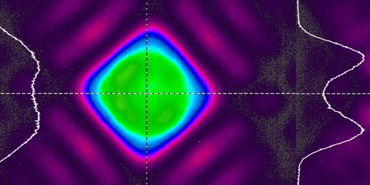
Fig. 2 shows cross-sections of the beam waist along the optical axis without (a) and with (b) an a|SqAiryShape as well as the colour representation of the square focal intensity distribution of the top-hat profile created in the focal point (c). Beam shaping takes place solely in the area of the focal point. The Gaussian distribution is clearly flatter (blue-shaded area) with the beam shaper (b) than without it (a).
Fig. 2: Different representations of the measured beam profile: (a) cross-section along the optical axis without an a|SqAiryShape, (b) cross-section along the optical axis with an a|SqAiryShape, (c) coloured representation of the measured squared focal intensity distribution.
 cross-section along the optical axis without an a|SqAiryShape, (b) cross-section along the optical axis with an a|SqAiryShape, (c) coloured representation of the measured squared focal intensity distribution.")
Project results
Testing the beam shaper with surface structuring
The beam shaper was tested in surface-structuring experiments by generating laser-induced periodic structures. LIPSSs are periodic patterns in the sub-µm range. They’re created by interference effects in the spot of the focused laser beam on the surface of the material, and in metals occur perpendicular to the linear beam position. Steel samples that had been ground, polished and cleaned beforehand with a mean square roughness of R_a=4 nm were used as substrate material. The experimental setup used during the structuring process is shown in Fig. 3. An fs laser [1] emitted linearly polarized light, which was expanded five-fold by an a|BeamExpander and modified using an a|SquAiryShape [2]. Finally, a galvanometer scanner [3] and an f-theta lens [4] were used to focus the beam into the desired processing zone [5].
Fig.3: Experimental setup in the surface-structuring experiments.

First of all, the characteristics of intensity distribution were measured without a beam shaper as reference values. To this end, the surface of the sample was irradiated with 10 pulses (f_rep=100 kHz) with a pulse energy of E_imp=6.5 µJ and a laser peak fluence of F = 2.9 J/cm², resulting in a focal spot diameter of 2wf = (24 ± 0.5) mm. To investigate melt formation when an a|SqAiryShape was used, ablation points were generated at different distances from the sample surface (z-axis) with a constant pulse energy of E_imp=6.5 µJ. The results were recorded using SEM (scanning electron microscopy) and are shown in Figure 4.
Fig.4: SEM images of sample surfaces in the area of focal intensity distribution after irradiation with 10 linearly polarized single fs pulses with a constant single pulse energy of E_imp=6.5 µJ each at different z-positions from the sample surface.

At the reference points z = 0 and z = –0.6 mm, the ablation points have square top-hat profiles, leading to square-shaped material ablation of 30 30 µm² (0.72 J/cm²) and 40 40 µm² (0.4 J/cm²) – ideal for laser material processing tasks. Compared to Gaussian focal points and assuming perfect rectangular intensity distribution, larger rectangular top-hat profiles with constant pulse energy lead to lower laser peak intensities. Furthermore, the a|SqAiryShape also offers other intermediate stages for additional, more unusual intensity distributions useful for generating novel structures.
At a position of z = –1.0 mm, doughnut-shaped intensity distribution can be observed, while at a position of z = –0.35 mm, the intensity distribution is completely reversed, with high intensity in the centre (beam waist). In addition, the SEM images show well-defined, homogeneous LIPSS distribution in the ablation spot, which essentially depends on the intensity distribution and thus on the z-position. The beam shaper therefore enables LIPSS distribution to be controlled by selecting the beam profile, ensuring high flexibility in the structuring process.
Furthermore, the formation of LIPSSs can be scaled to larger surfaces via the relative motion between the laser beam and the sample surface. Compared to structuring with a Gaussian beam profile, almost identical LIPSSs can be generated with lower laser pulse energies, higher scanning speeds (twice as fast) and scan line spacing using a top-hat beam profile (z = 0) with its square shape, larger beam diameter and steeper edges.
Qualitative study of how intensity distribution affects microstructuring
To study how the intensity distribution affects the surface structures produced and their surface quality, channels were produced with top-hat and doughnut profiles using different pulse energies. The results are shown in Figure 5. Top-hat and doughnut beam profiles can be used to produce steeper channel walls and above all better surface qualities in the bottom than Gaussian profiles. Particularly high surface qualities on the channel wall and bottom can be achieved by using moderate pulse energies with homogeneous intensity distributions across the beam profile (Figs. 5a & 5b). By contrast, high pulse energies and high laser peak intensities lead to rough, inhomogeneous surfaces on the bottom of the channel (Fig. 5c). The depth and width of channels can also be controlled by the pulse energy; they increase as the pulse energy rises (Fig. 5d).
Fig. 5: White light interferometry images of the sample surface showing the surface roughness to illustrate the 3D geometry of the channel-like structures (10 scans at v = 0.1 m/s using a top-hat profile and different pulse energies): a) E_imp=2.5 µJ, b) E_imp=4.6 µJ, c) E_imp=7 µJ, d) comparison of channel cross-sections.
: a) E_imp=2.5 µJ, b) E_imp=4.6 µJ, c) E_imp=7 µJ, d) comparison of channel cross-sections.")
When structuring large surfaces, the beam profile can be flexibly transformed into a square, doughnut-shaped beam profile (corresponding to the beam profile z = –0.9 mm in Fig. 4) by varying the distance from the sample surface (z-axis). Doughnut-shaped beam profiles have an intensity of almost zero in the centre, indicating that no high-intensity laser radiation reaches these areas and material removal there is very limited. This results in a cross-section with a W-shaped profile (Fig. 6c), which – assuming suitable scan line spacing – can be used to apply overlapping, nanoscale periodic patterns (LIPSS) with homogeneous, regular surfaces (Figs. 6a & 6b). In this example, channel widths of 40 µm and ablation depths of 10 µm were produced in this way with ten scans at a scanning speed v = 0.1 m/s and a pulse energy of E_imp= 4.6 µJ.
Fig.6: Microchannel produced on stainless steel using a square doughnut-shaped beam profile (z = –0.9 mm), 10 scans at v = 0.1 m/s, and a single pulse energy of E_imp= 4.6 µJ: (a) SEM image, (b) WLIM image, (c) cross-section of the height profile.
, 10 scans at v = 0.1 m/s, and a single pulse energy of E_imp= 4.6 µJ: (a) SEM image, (b) WLIM image, (c) cross-section of the height profile.")
Advantages of the a|SqAiryShape when structuring LIPSS
- High flexibility when generating various square beam profiles by altering the scan line spacing (z-axis)
- Quicker processing when structuring LIPSSs coupled with high process stability and low laser pulse energies
- Structuring of large areas
- Very regular periodicity of LIPSSs
- Produces steep, precise channel walls with high surface qualities
Further reading: Schlutow, H.; Fuchs, U.; Müller, F.A.; Gräf, S. Squared Focal Intensity Distributions for Applications in Laser Material Processing. In: Materials 2021, 14, 4981. https://doi.org/10.3390/ma14174981
To find out more about the principle of our a|SqAiryShape beam shaper, please go to asphericon.com/en/solutions/products/beamtuning/beam-shaping/